| |
|
|
| |
 This page is still under construction, I am using it as my
online notebook. This page is still under construction, I am using it as my
online notebook.
To Do It's time to finalize
and sort the content
on this page, but ...! ;-)
|
|
| |
|
|
| |
|
|
| |
|
|
| |
|
|
| |
"Die Einen kochen und kreieren leckere Gerichte; hier findet
man einige Zutaten zur Realisierung elektronischer Schaltungen."
mkn, 2013, ;-) |
|
| |
|
|
| |
Frequenzaufbereitung |
|
| |
|
|
| |
|
|
|
|
PLL Phasenregelschleife, Phase-Locked Loop
|
|
| |
|
|
| |
|
|
| |
-
Phasenregelschleife – Wikipedia |
|
| |
|
|
| |
Seminarvortrag Phase Locked Loop Phasenregelschleife by Janis Kruse
Arbeitsgruppe Schaltungstechnik und Simulation, Institut für Technische
Informatik (ziti), Universität Heidelberg |
|
| |
|
|
| |
|
|
| |
Funktion, Anwendungen
- Generierung
einer Frequenz, die Steuerung dieser Ausgangsfrequenz(VCO) durch eine
Eingangsfrequenz(REF)
- Stabilisierung, Umsetzung,
Vervielfachung, etc.
- Regelkreis mit einem Soll-Ist-Vergleich
- Demodulation von Signalen, Rückgewinnung von Signalinhalten |
|
| |
- Blockschaltbild
- Haupkomponenten
- VCO
- Teiler(optional, in Abhängigkeit der Applikation)
- REF-Frequenz
- Phasendiskriminator
- Regelkreis-Filter(loop filter)
- Fanghilfe
|
|
| |
|
|
| |
|
|
| |
-
Phase Locked Loop Circuits by Prof S. Long, 4/27/05, UCSB/ECE
Department
- detaillierte Einführung
-
zur Auffrischung ausgezeichnet geeignet
|
|
| |
|
|
| |
-
Phase-Locked Loop (PLL) Fundamentals by Ian Collins
|
|
| |
-
Converting Oscillator Phase Noise to Time Jitter by Walt Kester
|
|
| |
-
PLL
Performance, Simulation, and Design - Texas Instruments
-http://www.actel.kr/html/technote/pll/pll_performance_simulation_and_design.pdf
1998
|
|
| |
- Advanced Design System 1.5
PLL DesignGuide by , December 2000
|
|
| |
|
|
| |
|
|
| |
CMOS Micropower Phase-Locked Loop 4046 |
Phasen-Diskriminator, VCO,
Loop-Filter |
| |
|
|
| |
TI
CD4046B
description
CD4046B [July
2003]
TI Application
Report
ON Semiconductor
MC74HC4046A
RCA
CD4046A
NXP
74HC_HCT4046A |
Understanding
Buffered and Unbuffered
CD4xxxB Series Device Characteristics
|
| |
|
|
| |
- CD4046B
Phase-Locked Loop: A Versatile Building Block for Micropower Digital and
Analog Applications by TI, February 2003
-
Produktbeschreibung
- Applikationen: u.a. FM-Demodulation,
Frequency Synthesizer(REF: 1 kHz), PLL Lock Detection
|
|
| |
|
|
| |
-
CD54HC4046A, CD74HC4046A, CD54HCT4046A, CD74HCT4046A
by TI(HARRIS) February 1998 - Revised December 2003
-
ausführliches Datenblatt
|
|
| |
|
|
| |
- Implementation
of FSK Modulation and Demodulation using CD74HC4046A by TI, November
2013
|
|
|
-
Fractional/Integer-N PLL Basics by TI
-
- Loop
Filter
- |
|
| |
- Understanding
and Interpreting Standard-Logic Data Sheets by TI |
|
| |
|
|
| |
Phase Lock Loops |
MASSACHUSETTS INSTITUTE OF
TECHNOLOGY
Department of Electrical Engineering
|
| |
Phase Locked Loop MC14046B |
|
| |
CMOS RF SYNTHESIZER by Harry Lythall - SM0VPO |
|
| |
-
Ask the Applications Engineer—30, PLL SYNTHESIZERS, by Adrian Fox
[adrian.fox at analog.com]
|
->
Analog Dialogue, S.13
|
| |
|
|
| |
Phasendiskriminator XOR, PhD1, PC1 |
|
| |
|
|
| |
(VCC/π)*(φSIGIN
- φCOMPIN)
|
|
| |
|
|
| |
-
74HC 7046
- LOCK DETECTOR CIRCUIT
|
-
Switching Data
Book
|
| |
|
|
| |
-
74HC 9046
-
Datenblatt |
|
| |
-
74HC4046_7046_9046_CMOS_PLL_design_guide_Philips_1995_crop.pdf by
PHILIPS, today NXP, ...
- sehr informativ, wichtig, lesen
|
->
Manuals, Timing, Ham Radio, Test Equipment - KO4B |
| |
-
CMOS
Phase-Locked-Loop Applications Using the CD54/74HC/HCT4046A and
CD54/74HC/HCT7046A by TI
- die einzelnen
Funktiosgruppen wie phase comparators, lock indicators,
voltage-controlled oscillators (VCOs), und das loop filter
Design werden vorgestellt
- ausführlich wird das Prinzip des Lock
Detectors erläutert
|
Application Report
SCHA003B - September 2002 |
| |
-
Using 4046-Type PLLs Successfully by eevblog
|
|
| |
-
PLL-Frequenzsynthese: Spezielles Problem mit dem CD4046B (MC14046B) und
74HC4046 (-> Self-Bias-Circuit) |
Gibt es eigentlich nicht, wenn man
rechtzeitig auf die ergänzenden Hersteller-Informationen stößt oder ? |
| |
|
|
| |
Anwendungsbeispiele
- CD4046
-
in [1], Seiten 198-199: REF=10 kHz, PHD, Filter, Widerstand wegen Dead
Zone, DC-Siebung, zusätzliche LC-Filter
- in [1], Seiten 204:
REF=1 kHz, PHD, Filter, Widerstand wegen Dead Zone, DC-Siebung 100 uF am
CD4046, zusätzliche LC-Filter |
|
| |
- in [2] , Seiten 858-862: -->
Hinweis auf Dead Zone, Abhilfe |
|
| |
[1 ]"Arbeitsbuch für den HF-Techniker", Daten,
Fakten, HF-Grundschaltungen, 50-Ω-Technik, Eric Tart Red, 1986
Franzis-Verlag GmbH, München, Preis: 68 DM
- Einblick in die
professionelle Schaltungstechnik von Rohde&Schwarz
- Weiterbildung,
Anregungen und auch im Jahre 2017 in vielen Dingen lesenswert
-
praktische Beispiele zur Umsetzung
- 1990 erschien eine russische
Übersetzung im Verlag MIR,
Ред Э.Т. Справочное пособие
по высокочастотной схемотехнике: Схемы, блоки, 50-омная техника.
--->
Google weiß Bescheid
Im Beam-Verlag erschienen
HF-Module in 50-Ohm-Technik Eric T. Red, Reinhard Birchel, DJ9DV,
2003, 19,80 Euro, 18.11.2017 |
 |
| |
[2] Ulrich L. Rohde, David P. Newkirk: "RF/Microwave Circuit Design for Wireless
Applications", John Wiley & Sons, 2000
Die zweite Auflage erschien 2013. |
 |
| |
|
|
| |
|
|
| |
-
MC14044
- Phasendiskriminator
- applikative Hinweise |
|
| |
|
|
| |
|
|
| |
Gestaltung des Loop-Filters |
|
| |
|
|
| |
-
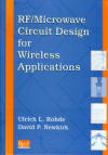
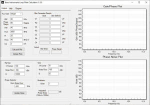
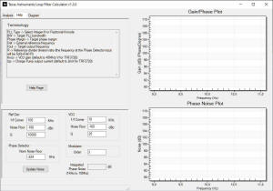
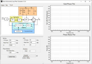
Loop Filter Calculation Tool by TI
- Installation unter Windows 10 gescheitert, 20.02.2020, mkn |
- 74hc4046 loop filter calculator -
Google-Suche |
| |
|
|
| |
 |
|
| |
 |
|
| |
|
|
| |
-
A survival guide to scaling your PLL loop filter design |
|
| |
|
|
| |
-
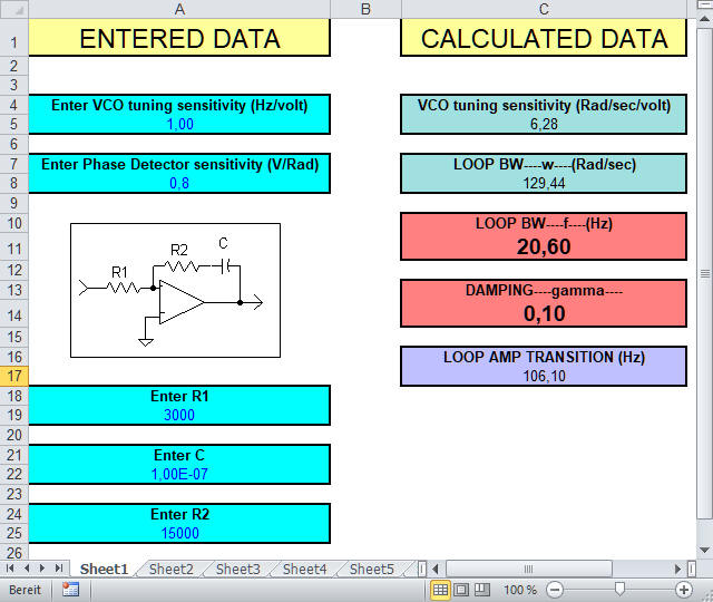
https://wenzel.com/documents/spread1.htm
- PLL Calculators by Wenzel
Associates, Inc.
Excel-Tabellenkalkulation zur Berechnung der Loop-Bandbreite und des
Dämpfungsfaktors einer analogen PLL des Types 2, mit aktivem PLL-Filter.
Eingabewerte:
- VCO tuning sensitivity
- loop components, R!, R2
und C
- phase detector sensitivity.
|
|
| |
|
|
| |
-
Don’t let bad reference signals destroy the phase noise in your
PLL/synthesizer |
|
| |
|
|
| |
-
Meinung zu GPS /
OCXO / PLL 10 MHz Frequenznormal
- EXOR
-
74HC4046 |
|
| |
|
|
| |
- CD4046B:
frequency synthesizer using CD4046B |
-
Phase_detector_note.pdf |
| |
-
https://e2e.ti.com/support/logic-group/logic/f/logic-forum/789519/cd4046b-cd4046b
|
|
| |
-
https://e2e.ti.com/search?q=cd74hc4046&category=forum
|
|
| |
- CD74HC4046A:
CD74HC4046A output can not be locked |
|
| |
- CD74HC4046A:
Clarification on CD74HC4046A to replace the reference CD4046BH
|
|
| |
|
|
| |
-
ADF 4001
-
Datenblatt |
|
| |
|
|
| |
- Quarzstabiler Mini-Bakensender für 313 kHz bis 200
MHz FA 2018 H. 12 S.1139ff
DC6HL
-
Si5351A
- verwendete Referenz 40 MHz ???
-
Layout im
FA-Downloadbereich |
|
| |
|
|
| |
Radio Station DF9NP HAM
PLLs ... PPS, Verteilverstärker, u.a.
-
Improving phase noise performance of the DF9NP 27MHz PLL
-
Le PLL Hyper de DF9NP
-
DF9NP PLL / simple 10GHz
test signal generator
-
Reprogrammation du GPSDO DF9NP |
- Preisliste, Schaltbilder |
| |
|
|
| |
============================================================================================ |
|
| |
|
|
| |
25-MHz-PLL by DF9NP |
|
| |
|
|
| |
- Freundlicher und kompetenter
Service, TNX an DF9NP. |
|
| |
|
|
|
Ub: 8-12 V
Ib: mA
RFout: 8,63 dBm
REF-Eingang 10 MHz:
Pegel bei 10MHz zwischen 1Vpp
und 2,5Vpp
Signalisierung:
LED1: Betriebspannung 5V
LED2: Lock
detect |
|
| |
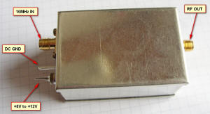
Bild: DF9NP |
Ein Blick unter den Deckel
|
| |
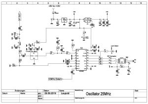 Bild:
DF9NP Bild:
DF9NP
ADF4001 200 MHz Clock Generator PLL
|
|
| |
 Messung: DF9NP
 |
|
| |
|
|
| |
|
|
| |
|
|
| |
|
|
| |
============================================================================================ |
|
| |
|
|
| |
ADF 4xxx Analog Devices
|
|
| |
|
|
| |
-
Fractional-N
Frequency Synthesizer ADF4153 Analog Devices
-
data sheet ADF4153.pdf
|
|
| |
-
ADF4153 12GHz PLL Umbau und Programmierung by
DL2OCB
- ADF4153 wird per
SPI programmiert
- Source Code
https://oe8woz.at/
-
https://oe8woz.at/Pro_Surplus.html
->
QSP_01_2018.pdf NORT PLL
|
|
| |
-
ADF435x PIC
|
|
| |
|
|
| |
|
|
| |
|
|
| |
|
|
| |
|
|
| |
-
https://www.analog.com/media/en/training-seminars/tutorials/adisimpll.pdf
|
|
| |
-
https://www.analog.com/media/en/analog-dialogue/volume-33/number-1/articles/volume33-number1.pdf
|
|
| |
- ADIsimPLL
-
ADIsimPLL PLL Circuit Design and
|
|
| |
|
|
| |
-
Download your free copy of ADIsimPLL |
|
| |
|
|
| |
|
|
| |
|
|
| |
|
|
| |
-
RF PLLs & synthesizers – Technical documents by TI
|
|
| |
|
|
| |
-
http://www.actel.kr/html/technote/pll/pll_performance_simulation_and_design.pdf
|
|
| |
-
PLL
Performance, Simulation, and Design, 5th Edition by Dean Banerjee
|
|
| |
-
http://eww.ko4bb.com/manuals/88.67.114.52/PLL_Performance_Simulation_Design_5th_BANERJEE_2017.pdf
|
|
| |
|
|
| |
-
Harmonic_content_of_various_periodic_signals.pdf
|
|
| |
|
|
| |
|
|
| |
--->
LO PLL USB ADF4351
50 - 4400 MHz |
|
|
|
|
| |
|
|
| |
--->
PLL als
Frequenz-Vervielfacher |
|
| |
|
|
| |
|
|
| |
============================================================================================ |
|
| |
|
|
| |
PLL zur jitterfreien Anbindung eines VCO(OCXO) an eine
verjitterte Referenzfrequenz
|
|
| |
- |
|
| |
- AN513
JITTER ATTENUATION — CHOOSING THE RIGHT PHASE - LOCKED LOOP BANDWIDTH
--> Hier wird die Aufgabenstellung der jitterfreien
Anbindung eines VCO an eine verjitterte Referenzfrequenz betrachtet.
-
Phase Noise to Jitter Calculator by Silicon Laboratories
|
|
| |
- AN1282
Board
Strategies for Ensuring Optimum Frequency Synthesizer Performance By
Robert S. Jones III
- Phase Noise from Reference Signal
- Kondensatoren zur Abblockung der Abstimmspannung
- Star
Point Power Supply Connection
- Star Point Power Supply
Connection Strategy with First Order Filters, ..., RC-Filter
-
"Noise is commonly coupled to analog nodes via routing. When digital
traces run parallel or even overlap analog signals on a
multi-layer board,the digital signals may be inductively or capacitively
coupled to the analog signals."
- ...
- Ensure flux
is properly washed off board
|
|
| |
|
|
| |
-
https://www.ti.com/lit/ml/snap003/snap003.pdf
|
|
| |
|
|
| |
-
What are the 8 Most Important Oscillator Specs? by JIM HOLBROOK
-
Glossary of Oscillator Terminology
-
Clock Jitter Definitions and Measurement Methods
-
Phase Noise Measurement Guide for Oscillators
|
|
| |
-
Impact of PLL Jitter to
GSPS ADC's SNR and Performance Optimization
-
https://www.ti.com/rf-microwave/rf-plls-synthesizers/technical-documents.html#
|
|
| |
|
|
| |
|
|
| |
|
|
| |
|
|
| |
-
How to estimate the phase noise of a PLL with basic datasheet
specifications
|
|
| |
-
Phase Noise of Integer-N and Fractional-N PLL Synthesizers
by Kevin Scott and Michel Azarian |
|
| |
|
|
| |
|
|
| |
|
|
| |
============================================================================================ |
|
| |
|
|
| |
Phasendetektor ExOR
|
https://www.google.com/search?q=phase+xor
|
| |
|
|
| |
-GPSDO
with XOR phase comparator - control loop filter design by |
|
| |
-
https://github.com/igor-m
-
XOR GPSDO CONTROL LOOP DESIGN
|
|
| |
|
|
| |
-
Detect Phase
Differences in Input Signals - YouTube by TI
"Ein
Phasendetektor gibt ein PWM-Signal aus, das die Phasendifferenz zwischen
den Eingangssignalen darstellt.
Dieses Video erklärt,
wie ein XOR-Gatter als Phasendetektor funktioniert."
->
Logic Circuit |
Overview | Design Challenges | TI.com |
|
| |
-
AD8302 (Rev. B) (analog.com) |
|
| |
-
How does an XOR phase difference detector behave when input frequencies
are different?
|
-
AD8302 (Rev. B) (analog.com) |
| |
-
Falstad Sim of XOR PLL |
-
Paul Falstad |
| |
|
|
| |
-
PD/Divider Tab (keysight.com)
-
GENESYS 2008 Help (keysight.com)
-
W1323BP Genesys Core, System Bundle | Keysight |
|
| |
|
|
| |
-
PLL
by
w2aew
-
Basics_of_PLLs.pdf (qsl.net) |
|
| |
|
|
|
-
74HC 86 XOR-Gate, 2-Input, 2 ... 6 V, DIL-14 Quadruple
2-Input Exclusive-OR Gates, Vierfache
2-Eingangs-Exklusiv-ODER-Gatter
Datenblatt |
|
|
74HC86 = M74HC86 =
SN74HC86 |
|
| |
|
|
| |
Projekt 25 MHz PLL |
|
| |
25-MHz-VC-OCXO |
|
| |
Fref = 10 MHz , Quelle:
10-MHz-GPSDO |
|
| |
Ziel, Anwendung: 25 MHz Signal für
LNB, QO-100-Anwendung |
|
| |
- KISS, simple |
|
| |
- Fref : 2 -> 5MHz
- Focxo : 5
-> 5 MHz
- Phasenvergleich auf 5 MHz
- Phasendiskriminator: XOR
|
Kommerzielle Umsetzung dieses
Prinzips
-DxPatrol
-
DX-Patrol QO-100 Down Converter |
| |
|
|
| |
|
|
| |
|
|
| |
|
|
| |
|
|
| |
============================================================================================ |
|
| |
|
|
| |
ADF4351 |
|
| |
|
|
| |
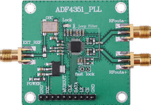
-
WALFRONT 35
Mt-4,4 GHz RF Signalquelle Phase Locking Loop Frequenz Synthesizer
ADF4351 Entwicklungsboard: Amazon.de
|
Bild |
| |
|
https://www.amazon.de/Entwicklungsboard-Frequenzsynthesizer-35M-4-4GHz-Signalquelle-Locking/dp/B07DG15YL8/
|
| |
Technische Aussagen zum Produkt
durch den Verkäufer |
|
| |
|
|
| |
RF-Ausgangsfrequenzbereich: 35M
bis 4,4GHz,
Standard + -50ppm 25M
aktiver Quarzoszillator. Bestückt mit 10 MHz XO
! [mkn]
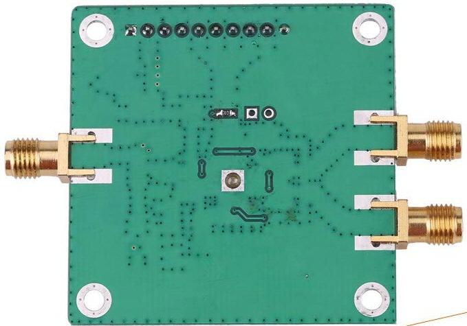
Diese ADF4351-Signalquellen-Entwicklungsplatine
verfügt über ein durchdachtes Leiterplattenlayout.
Der
Frequenzsynthesizer kann von der offiziellen Software des oberen
Computers gesteuert werden.
Alle Steuerstifte sind zur bequemen
Bedienung herausgeführt.
Dreiadriges serielles
Peripherieschnittstellen-Buskabel zum Steuern des Stiftes und
Zustandsverriegelungsstift, wodurch alle Funktionen einschließlich
Punktfrequenzabtastung und Frequenzsprung ermöglicht werden. |
|
| |
|
|
| |
Eigenschaften:
Diese
ADF4351-Signalquellen-Entwicklungsplatine verfügt über ein durchdachtes
Leiterplattenlayout.
Es kann von der oberen Computer
offiziellen Software gesteuert werden.
Alle Steuerstifte
sind zur bequemen Bedienung herausgeführt.
Standard +
-50ppm 25M aktiver Quarzoszillator.
Spezifikationen:
Ausgangsfrequenzbereich: 35 MHz - 4,4 GHz
Versorgungsspannung: 4-9V (5VDC)
Ausgangssignal:
2,2 GHz - 4,4 GHz Sinuswelle (Grundwelle)
35 MHz -
2,2 GHz Rechteck (Grundteilung)
Ausgangssignal:
Ausgangsgeschwindigkeit, Signalstärke: + 5dBm (programmierbar)
HF-Anschluss: SMA-Buchsenkopf
Steuerschnittstelle: Dreiadriger serieller
Peripherieschnittstellenbus
Referenzuhr: 10.000 MHz
(Standard), über die Schnittstelle zu einem externen SMA
Größe: Ca. 4,8 x 4,9 cm / 1,89 x 1,93 Zoll
Gewicht: 15g
Verbindung:
Das Modul kann
Mikrocontroller LCD1602 / LCD12864 Modulanschluss (kann direkt rückwärts
gesteckt werden), bequeme Software-Debuggen, beide Lock-Indikator
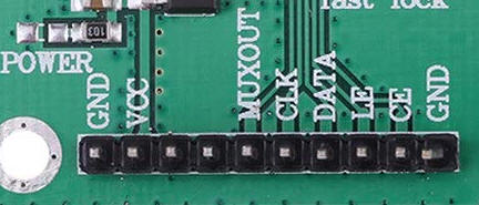
(Lock). Pin entspricht folgendem:
1.GND -- GND
2.VDD (5V) -- VCC
3.VO -- NC (leer)
4.RS -- NC (leer)
5.R / W -- MUXOUT
6.DE -- CLK
7.DB0 -- DATEN
8.DB1
-- LE
9.DB2 -- CE (hat 10K Pullup)
10.DB3 -- GND (nicht nehmen)
RF-Ausgang:
Zur
Vereinfachung der Verwendung ist die Standardeinstellung eine
Breitbandausgabe, die Ausgabe von zwei Differenzsignalen, ein Weg kann
zur Ausgabe verwendet werden, der andere Weg kann verwendet werden, um
den Ausgang zu überwachen.
Lieferinhalt:
1 x
ADF4351 Frequenz-Synthesizer |
|
| |
|
|
| |
-
Frequenzsynchronisation (QO100 LNB und Pluto SDR) mit GPSDO, ADF4351 und
Arduino |
|
| |
-
GPSDO Stabilisierung für 25MHz LNBs und Adalm Pluto SDR by
OE5RNL , 20190809
-Arduino-SourceCode
|
|
| |
-
Den ADF4351 Frequenzgenerator 35MHz bis 4,4GHz vom Arduino Uno ansteuern
by Matthias Busse
|
|
| |
-
Datenblatt ADF4351 |
|
| |
-
Evaluation Board User Guide UG-435
|
|
| |
-
Ein Tiefpaßfilter 5. Ordnung mit 69 MHz aufgebaut für den ADF4351
|
|
| |
|
|
| |
 |
In der Beschreibung wird von einem
25 MHz XO gesprochen |
| |
|
|
| |
 |
|
| |
|
|
| |
1 GND |
|
| |
2 VCC: +5 V |
Spannungsregler LDO 5 V auf 3,3
Volt |
| |
3 NC not conected |
|
| |
4 NC not conected |
|
| |
5 MUXOUT
Multiplexer Output.
The multiplexer output allows the lock detect value, the N divider value,
or the R counter value to be accessed externally. |
|
| |
|
|
| |
6 CLK Serial Clock Input. Data is
clocked into the 32-bit shift register on the CLK rising edge. This
input is a high impedance CMOS input.
|
Achtung Pegel max 3,3 Volt! |
| |
7 DATA Serial Data Input.
The serial data is loaded MSB first with the three LSBs as the control
bits. This input is a high impedance CMOS input.
|
|
| |
8 LE Load Enable. When LE goes
high, the data stored in the 32-bit shift register is loaded into the
register that is selected by the three control bits. This input is a
high impedance CMOS input.
|
|
| |
9 CE Chip Enable. A logic low on
this pin powers down the device and puts the charge pump into
three-state mode.
A logic high on this pin powers up the device,
depending on the status of the power-down bits. |
10 kOhm Pullup Widerstand zu +3,3
V
- 5V möglich? |
| |
|
|
| |
10 GND |
|
| |
|
|
| |
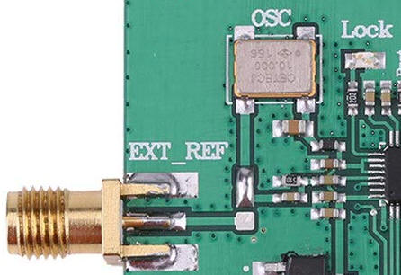
REFIN Reference Input des ADF4351
This CMOS input has a nominal threshold of AVDD/2 and a dc equivalent
input resistance of 100 kΩ. This input can be driven from a TTL or CMOS
crystal oscillator, or it can be ac-coupled. |
|
| |
|
|
| |
SW Fast Lock Switch. A connection
should be made from the loop filter to this pin when using the fast lock
mode. |
|
| |
|
|
| |
 |
|
| |
Umschaltung auf externe
Referenzfrequenz |
|
| |
 |
|
| |
|
|
| |
CETECJ 10.000
156 Taitien
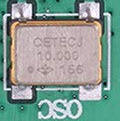
Model-Numbering-Guide_XO-Rev307-2015.pdf
C 3,3 V
https://www.taitien.com/wp-content/uploads/2019/05/XO-0166_PC-U.pdf
 |
view inside |
| |
Application Notes |
|
| |
|
|
| |
|
|
| |
Arduino - Arduino Board
ProMini |
|
| |
-
Pro Mini 3V 8 MHz
ATmega328P Arduino kompatibel. low power
|
|
| |
|
|
| |
-
ADF4351 driven RF Generator 34.5 to 4400MHz by an Arduino By Alain
Fort F1CJN, March 7, 2016
-
https://github.com/F1CJN
- ADF4351 synthetizer board driven by
an ARDUINO and LCD KEYPAD SHIELD Module |
|
| |
|
|
| |
|
|
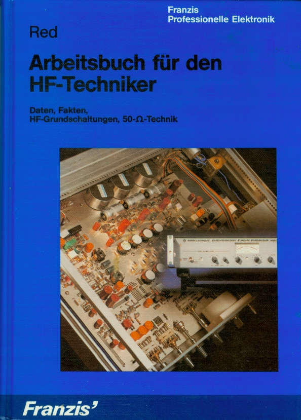
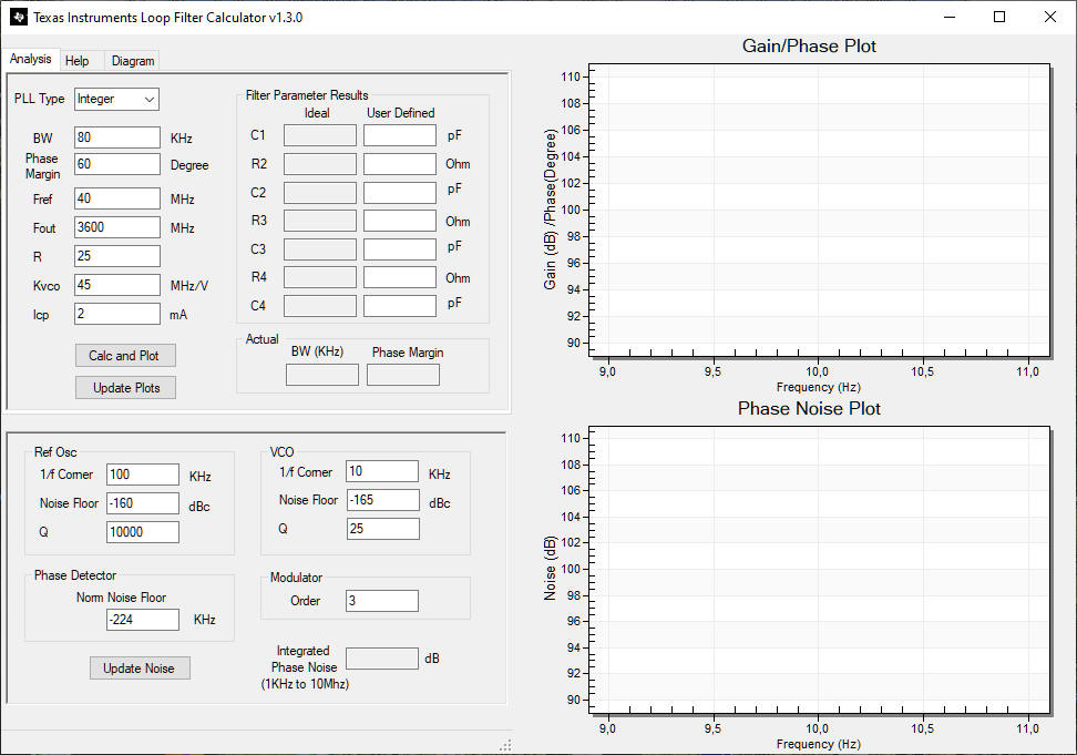
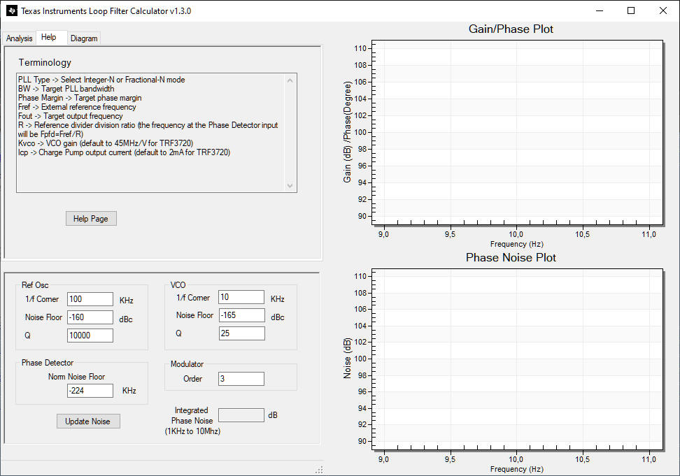
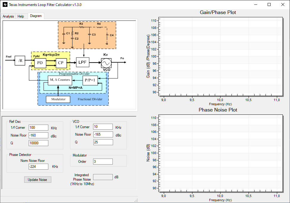

 Bild:
DF9NP
Bild:
DF9NP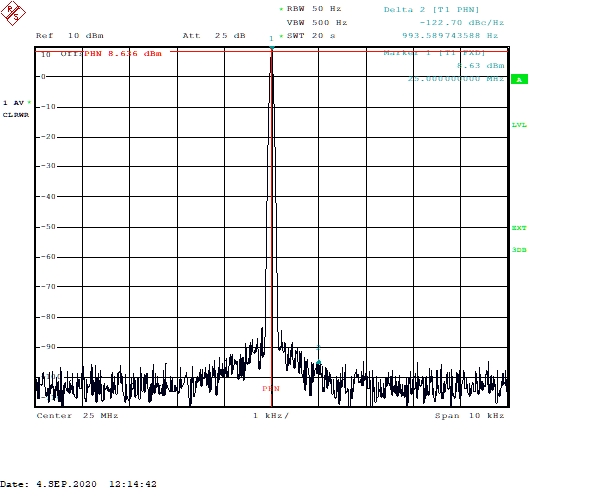 Messung: DF9NP